RTK
- Objectif :Création d'une géolocalisation Centimétrique à faible coût
Le fonctionnement
Le matériel
| Chapitre | Sous-Chapitre | Image | Désignation | Fournisseur | Prix | Stock |
|---|---|---|---|---|---|---|
| Modules | Capteur de position | 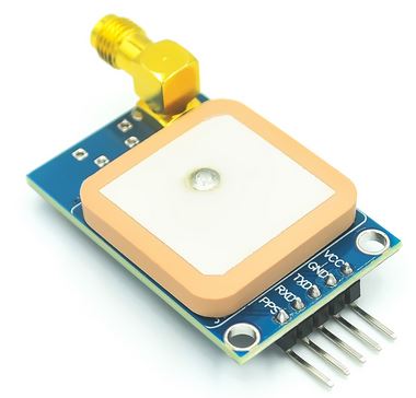 | NEO-8M Module GPS GPS8MV2, NEO8M avec EEPROM APM2.5 | aliexpress | 8,3€ | 2 |
| Modules | Capteur de position | 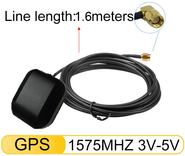 | Hoxiao-Antenne GPS de voiture, connecteur SMA, câble de 1.6m | aliexpress | 2,245€ | 2 |
| Microcontrolleurs | Micro contrôleur 32 bits | 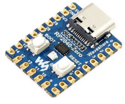 | RP2040-Zero, une carte MCU basée sur le microcontrôleur Raspberry Pi RP2040
| aliexpress | 5,47€ | 2 |
Les configurations
Avant tout il faut configuer le NEO-8M :télécharger la dernière version de l'application u-center sur votre PC : https://www.u-blox.com/en/product/u-center
Brancher le port USB-micro B sur NEO-8M et sur le PC.
Dans l'application u-center, connecter vous à votre NEO-8M https://www.u-blox.com/en/product/neo-m8-series?legacy=Current#Documentation-&-resources
 | Dans le menu receiver, connection. |
Mettre à jour le firmware
Verifier votre version : View → Messages View → Onglet UBX → MON(Moniteur) → VER(Version)Sur le site de u-center, verifier la dernière version.
Pour mes NEO-8M, actuellement :
Software Version : EXT CORE 3.01 (107900)
Harware Version : 00080000
Extensions : ROM BASE 2.01 (75331)
FWVER=SPG3.01
PROTVER=18/00
MOD=NEO-M8N-0
Configurer la base
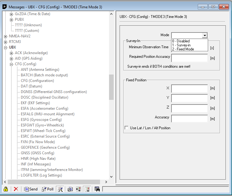
Les deux cartes sont identiques. Sélectionnez une carte pour faire office de « Station de base ».Il y a trois étapes pour configurer la station de base :
- Définissez la position en demandant à la station de base d'effectuer l'une des opérations suivantes :
- recherche des coordonnées
- être configuré avec des coordonnées pré-définies
- Configurez le port pour la configuration de la transmission de données
- Sélectionnez les messages RTCM à transmettre
Tout se passe dans View → Messages View → Onglet UBX → CFG(Config) → TMODE3(Time mode 3)
 |
Commencer une auto-enquète (Survey-in)
|
Les coordonnées de la station de base
Étape 1 – Les coordonnées de la station de base• Le message UBX-NAV-SVIN View → Messages View → Onglet UBX → NAV(Navigation) → SVIN(Survey-in)
vous permet pour surveiller le processus d'enquête.
• L'auto-enquête se termine lorsque la précision ET le délai est respecté.
Capteurs
- Objectif :Déscription des capteurs
Les différents type de capteurs
La déscription suivante est en TTL avec des alimentations 5V.Le signal de récéption sera toujours sur un attiny85 PB2/Int0, celui-ci est bien entendu adaptable sur d'autre systèmes.
infrarouge à led
Capteur infrarouge à fourche
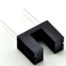 |
Capteur de champ magnétique
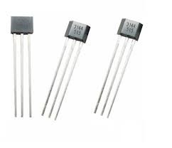
Capteur effet Hall Y3144 4.5-24V, Détecteur magnétique. |
Capteur de lumière
Câblage toujours avec une résistance de tirage. | 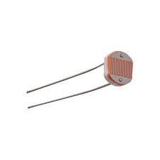 |
Bouton poussoir
| Avec un seul poussoir, l'entrée est tirée à la masse via une résistance de 10kΩ.
L'appui sur le poussoir amène cette entrée à 5V. Ceci permet d'avoir un signal propre, en effet, si nous laissons un bouton poussoir, sans connection le signal peut-être influencé par un champ extérieur. |
Fréquencemètre/Tachymètre
- Objectif :Mesurer la fréquence
- Moyen:
- Processeur Attiny85 - 20Mhz
- Batterie 852540 3.7V
- Afficheur Oled 128x64 1.3" ou 0.96"
- 1 LED Infrarouge IR 940nm Émetteur Ø5mm
- 2 LED Infrarouge IR 940nm Récepteur Ø3mm
- 2 résistances 1/4W 1kΩ
- 1 résistances 1/4W 120Ω
- 2 SS1200G3 Bouton Interrupteur 0.5A 50 V DC
- 1 Bouton-poussoir/interrupteur 6x6x7mm 4 Pin DIP Contact
Méthode
- Le microcontroleur attend une interuption sur la broche PB2.
- Commence le comptage sur 32 bits des impulsions sur PB2 et demarre le chrono
- Au bout d'une seconde, STOP le chrono et le comptage
- Convertion pour l'affichage Hexadécimal -> DCB ascii
- Affichage sur Oled la valeur de comptage
- multiplie la valeur par 60
- Affichage sur Oled de la valeur en tr/min

La fréquence maximale mesurable est d'environs 6000000Hz soit 6MHz, pour un petit microcontroleur, c'est déjà bien non!
Programme
Le bouton reset pour mettre le compteur à zero; ATtiny45 - 20MHz interne ; +-\/-+ ; PB5 1|- -|8 Vcc ; RESET PB3 2|- -|7 PB2 T0/Int0 entrée signal ; SENS PB4 3|- -|6 PB1 SDA OLED 128x32 ; GND 4|- -|5 PB0 SCL OLED ; +----+
main.asm
    ;
; Frequencemetre.asm
;
; Created: 28/07/2020 12:52:11
; Author : samuel.dupre
;
;        ATtiny45 - 8MHz interne
;             +-\/-+
; 	     PB5 1|-  -|8  Vcc
;		 PB3 2|-  -|7  PB2 T0/Int0 entrée signal
;   	 PB4 3|-  -|6  PB1 SDA OLED 128x32
;		 GND 4|-  -|5  PB0 SCL OLED
;             +----+

/*
.device atmega328p
.nolist
.include  "m328pdef.inc"			; definitions for the Atmega 328
*/
.device attiny85
.nolist
.include  "tn85def.inc"			; definitions for the Atmega 328
.list
;.def regC	= R25		; GENERAL PURPOSE ACCUMULATOR
;.equ	PN532_I2C	= 0x24	;Adresse I2C
;.equ	PN532_HOSTTOPN532 = 0xD4
#define F_CPU  16000000 // Clock Speed
;#define freq_timer1 1		;Hz
;#define timer1_counter 65536-(F_CPU/256/freq_timer1)
#define	nbrint	61		;nombre d'interruptions pour un comptage  Ti= (1024*256)/16 =16384?s x61= 999424?s soit environs 1s
;#define DEBUG		;si test via uart
;#define fontcp437	;si omis font5x8
;count  r5:r4:r3:r2
.def	DATA	=r20
.def	regA	=r16
.def	regB	=r17
.def	regC	=r18
.def    tmp		=r19
.def	zero	=r10
.def	countLL =r11
.def	countLH =r12
.def	countHL =r13
.def	countHH =r14

;ZH:ZL  r31:r30
;YH:YL  r29:r28
;XH:XL	r27:r26
;Pour temps
.def	VH		=r25	;nombre d'interruption
.def	VL		=r24
.def	WH		=r23	;min
.def	WL		=r22	;sec


.def	State=r21

;Pour affichage et son
.equ	buzz	=PB1
.equ  	SENSELED=PB5   ;  SENSELED pin (Output on AVR)

.macro   ldz
	ldi 	zl, LOW(@0<<1)
	ldi		zh, HIGH(@0<<1)
.endm
.macro   ldy
	ldi 	yl, LOW(@0)
	ldi		yh, HIGH(@0)
.endm
.dseg
.org	0x60
count:		.byte 4		;32 bits

in_buf:
lne:		.byte 30	;50 si usart, 30 si pas usart
fin_ram:
buffermax:	.byte 8*5	;4 pour l'affichage 1 pour le scroll
Buffer:		.byte 100	;Pour buffer bluetooth
.cseg
.org 0000
;************************************************
;* Interrupt Vectors				      *
;************************************************
	rjmp		main	; Reset Handler
	reti		; External Interrupt 0
	reti		; Pin change Interrupt Request 0
	reti		; Timer/Counter1 Compare Match 1A
	rjmp		TIMER1_OVF		; Timer/Counter1 Overflow
	rjmp		TIMER0_OVF		; Timer/Counter0 Overflow
	reti		; EEPROM Ready
	reti		; Analog comparator
	reti		; ADC Conversion ready
	reti		; Timer/Counter1 Compare Match B
	reti;rjmp		TIMER0_COMPA		; Timer/Counter0 Compare Match A
	reti		; Timer/Counter0 Compare Match B
	reti		; Watchdog Time-out
	reti		; USI START
	reti		; USI Overflow

main:
	ldi		regA,high(RAMEND)	; set up stack pointer
	out		SPH,regA
	ldi		regA,low(RAMEND)
	out		SPL,regA
	ldi		regA,(1<<CLKPCE)	; enable the clock prescaler
	sts		CLKPR,regA		; for 4 cycles
	clr		regA
	sts		CLKPR,regA		; and div factor to 1
	clr		zero
	rcall	SSD1306_INIT
loop:
	;rcall	start_count

	;------------------------------ test
	ldi		regA,BYTE4(12321)
	mov		r5,regA
	ldi		regA,BYTE3(12321)
	mov		r4,regA
	ldi		regA,BYTE2(12321)
	mov		r3,regA
	ldi		regA,BYTE1(12321)
	mov		r2,regA
	rcall	BIN2DCB32
;------------------------------ fin test
	clr		posX
	clr		posY
	rcall	ssd1306_setpos
	ldi		zh,high(lne)		; formatted line image
	ldi		zl,low(lne)
	rcall	ssd1306_write_string


	ldi		regA,1
	rcall	waitseconds
	rjmp	loop
	;freq = count*16000000/(nbrint*1024*256);
	;freq= count* 15625/(nbrint*256); si nbrint=61 interruption pour une seconde
	;freq= count
	rcall	BIN2DCB32
	clr		posX
	clr		posY
	rcall	ssd1306_setpos
	ldi		zh,high(lne)		; formatted line image
	ldi		zl,low(lne)
	rcall	ssd1306_write_string
	rjmp	loop


start_count:
;count = 0	;la variable count représente le nombre d’impulsion qui généra par  le timer 1
	clr		countHH	;high H
	clr		countHL	;high L
	clr		countLH	;low H
	clr		countLL	;low L
	clr		r2
	clr		r3
	clr		r4
	clr		r5
	cbi		DDRB,2
; Clear registers
;Timer/Counter 0 initialization comptage sur T0
;TCCR0A=0;  (0<<COM0A1) | (0<<COM0A0) | (0<<COM0B1) | (0<<COM0B0) | (1<<WGM01) | (0<<WGM00)
	;ldi		regA,(0<<COM0A1) | (0<<COM0A0) | (0<<COM0B1) | (0<<COM0B0) | (1<<WGM01) | (0<<WGM00)
	;out		TCCR0A,regA
	out		TCCR0A,zero
	out		TCNT0,zero
	;ser		regA
	;out		OCR0A ,regA	;tous les 255 T0


;Timer/Counter 0 Interrupt(s) initialization compteur
	ldi		regA,(0<<OCIE1A) |(0<<OCIE1B) |(0<<OCIE0A) | (0<<OCIE0B) | (1<<TOIE1) | (1<<TOIE0) ; TOIE0: Timer/Counter0 Overflow Interrupt Enable
	out		TIMSK,regA

; Timer/Counter 1 initialization
;TCCR1A=(0<<COM1A1) | (0<<COM1A0) | (0<<COM1B1) | (0<<COM1B0) | (1<<WGM11) | (0<<WGM10)
;CTC	top:OCR1	Clear Timer on Compare Match  prescaler = 1024
	ldi		regA,(0<<CTC1) | (0<<PWM1A) | (0<<COM1A1) | (0<<COM1A0) | (1<<CS13) | (0<<CS12) | (1<<CS11)  | (1<<CS10)
	out		TCCR1,regA
;TCNT1=0x00
	out		TCNT1,zero
;OCR1A=0xFF
	ser		regA
	out		OCR1A,regA
;ni = 0 compteur d'interruptions
	clr		VL
	clr		VH
	sei		;activation des interruptions
	ldi		regA,(1 << CS02) | (1 << CS01) | (1 << CS00)	;External clock source on T0 pin. Clock on rising edge
	out		TCCR0B,regA
	ret

TIMER0_OVF:
;add count+1
	push	regA
	in      regA,SREG
	push    regA
	ldi		regA,1
	add		countLH,regA			;(count+1) high
	adc		countHL,zero			;(count+2)
	adc		countHH,zero			;(count+3)
	pop		regA
	out		SREG,regA
	pop		regA
	reti
;Timer1 overflow interrupt service routine
;Toutes les 16384us
TIMER1_OVF:
	push	regA
	in      regA,SREG
	push    regA
	;ni++
	adiw	VL,1
	cpi		VL,low(nbrint)
	ldi		regA,high(nbrint)
	cpc		VH,regA  ;nombre d'interruptions pour un comptage
	brne	no_ni_egal
	in		countLL,TCNT0	;count Low L
	mov		r2,countLL
	mov		r3,countLH
	mov		r4,countHL
	mov		r5,countHH
	out		TCNT0,zero
no_ni_egal:
	pop		regA
	out		SREG,regA
	pop		regA
	reti

.include "wait.inc"
.include "oled.inc"
BIN2DCB32.inc
    ;32-bit unsigned binary integer to 8-bit BCD in AVR ASM for ATtiny
;Entrée : r5:r4:r3:r2
;Sortie : r9:r8:r7:r6
; .def	regA  =	  r16
; .def 	r10=r8
; .def	regC=r17
BIN2DCB32:
	push	zh
	push	zl
	push	regA
	push	regB
	push	regC
	push	r2
	push	r3
	push	r4
	push	r5
	push	r6
	push	r7
	push	r8
	push	r9
	push	r10
		ldi		zh,high(lne)		; formatted line image
		ldi		zl,low(lne)
		clr		r6
		clr		r7
		clr		r8
		clr		r9

		LDI		regC,32	;Compteur de bit 32 shift
BCD8:	;8 octals
		lsl		r2			;peu importe le carry
		ROL		r3
		ROL		r4
		ROL		r5
		ROL		r6
		ROL		r7
		ROL		r8
		ROL		r9
		dec		regC
		brne	tst8o		;si <>32 test sinon ret

		mov		regA,r9
		rcall	DCB4
		mov		regA,r8
		rcall	DCB4
		mov		regA,r7
		rcall	DCB4
		mov		regA,r6
		rcall	DCB4
		pop		r10
		pop		r9
		pop		r8
		pop		r7
		pop		r6
		pop		r5
		pop		r4
		pop		r3
		pop		r2
		ldi		zh,high(lne)		; formatted line image
		ldi		zl,low(lne)
		;supprime Zero départ
	sup0:
		ld		regA,Z
		cpi		regA,0
		breq finsupp
		cpi		regA,'0'
		brne	finsupp
		ldi		regA,' '
		st		Z,regA
		adiw	ZL,1
		rjmp	sup0
	finsupp:
		;rcall	lne_usart
		pop		regC
		pop		regB
		pop		regA
		pop		zl
		pop		zh
		ret

DCB4:
		swap	regA
		mov		regB,regA
		andi	regB,0x0F
		ori		regB,0x30
		st		Z+,regB
		swap	regA
		mov		regB,regA
		andi	regB,0x0F
		ori		regB,0x30
		st		Z+,regB
		st		Z,zero
		ret


tst8o:	mov		r10,r6
		rcall	tst2o		;rcall test 2 octals
		mov		r6,r10

		mov		r10,r7
		rcall	tst2o		;rcall test 2 octals
		mov		r7,r10

		mov		r10,r8
		rcall	tst2o		;rcall test 2 octals
		mov		r8,r10

		mov		r10,r9
		rcall	tst2o		;rcall test 2 octals
		mov		r9,r10
		rjmp 	BCD8

tst2o:	ldi		regA,0x0F
		and		regA,r10
		cpi		regA,5
		brlo	tst1o		;regA<5 test 1 octal bas
		ldi		regA,0x03		;si>=5 enlève 0x03
		add		r10,regA
tst1o:	ldi		regA,0xF0
		and		regA,r10
		swap	regA
		cpi		regA,5
		brlo	endtst2o	;regA<5 test 1 octal haut
		ldi		regA,0x30
		add		r10,regA	;si>=5 enlève 0x30
endtst2o:
		ret
i2c.inc
; IO Port Bits
.equ	bSDA		= PB4	;* SCL Port B, PB1 Pin 6
.equ	bSCL		= PB3	;* SDA Port B, PB0 Pin 5
.equ	mSDA		= (1<<bSDA) ;Calculate binary value corresponding to I/O port bit for masking
.equ	mSCL		= (1<<bSCL) ;Calculate binary value corresponding to I/O port bit for masking

;Port C
.equ	I2CPORT 	= PORTB	;*Set to correspond to I/O Port used for I2C
.equ	I2CDDR  	= DDRB	;*Set to correspond to I/O Port used for I2C
.equ	I2CPIN  	= PINB	;*Set to correspond to I/O Port used for I2C

; delay half period
; For I2C in normal mode (100kHz), use T/2 > 5us
; For I2C in fast mode (400kHz),   use T/2 > 1.25us
#define	I2C_speed   int(F_CPU*1.5/4000000)	;1.5us
;Pour l'I²C
.ifndef DCounter
	.def DCounter=r8;
	.message "DCounter vient d'etre defini!"
.else
	.message "AM3220:DCounter est deja defini!"
.endif
.ifndef DATA
	.def DATA=r18;Read/Write data
	.message "DATA vient d'etre defini!"
.else
	.message "AM3220:DATA est deja defini!"
.endif


;xxxxxxxxxxxxxxxxxxxxxxxxxxxxxxxxxxxxxxxxxxxxxxxxxxxxxxxxxxxxxxxxx
;		START I2C ROUTINES
;xxxxxxxxxxxxxxxxxxxxxxxxxxxxxxxxxxxxxxxxxxxxxxxxxxxxxxxxxxxxxxxxx
;-----------------------------------------------------------------

;*************************************************************************
; delay half period
; For I2C in normal mode (100kHz), use T/2 > 5us
; For I2C in fast mode (400kHz),   use T/2 > 1.25us
;*************************************************************************
I2CDelay:
	ldi		XH,HIGH(I2C_speed) ;5us
	ldi		XL,LOW(I2C_speed)
	rcall	Wait4xCycles
	ret								 ; 4 cycle = total 60 cycles = 5.0 microsec with 8 Mhz crystal

;-----------------------------------------------------------------
I2CInit:
	; Set up port assignments
	sbi		I2CDDR,bSCL		; SCL only output by default
	sbi		I2CPORT,bSCL	; SCL outputs high, input pullups disabled
	cbi		I2CPORT,bSDA	; Data line always drives low if driven
	cbi		I2CDDR,bSDA		; SDA as input to start with - floats high
	cbi		I2CPORT,bSCL	; Set SCL low to try and avoid...
	sbi		I2CDDR,bSCL		; ...false start transitions
	rcall	I2CDelay
	rjmp	I2CStop			; Stop any erroneous transfer


;-----------------------------------------------------------------
; I2CStart
; Send I2C start condition
; Assumes SCL and SDA are high to start with.
; Leaves SCL and SDA low
I2CStart:
	rcall	I2CDelay
	sbi		I2CDDR,bSDA		; Drive data line low (start bit)
	rcall	I2CDelay
	cbi		I2CPORT,bSCL	; Clock line low (ready to start)
	ret
;-----------------------------------------------------------------
; I2CStop
; Send I2C stop condition
; Assumes SCL is low to start with, SDA may be in either state
; Leaves SCL and SDA high
I2CStop:
	sbi		I2CDDR,bSDA		; SDA driven low
	rcall	I2CDelay
	sbi		I2CPORT,bSCL	; Clock line high (ready to stop)
	rcall	I2CDelay
	cbi		I2CDDR,bSDA		; Data line floats high (stop bit)
	rcall	I2CDelay
	ret

;-----------------------------------------------------------------
;DATA_write_byte
;	DATA byte
;	ADR	 adresse byte
DATA_write_byte:
	mov		regA,DATA			; save value
	rcall	I2CStart
	ldi		DATA,(SSD1306<<1)
	rcall	I2CSendAddress
	brne	WriteI2cNoAck	; No ack!
	mov		DATA,regA
	rcall	I2CSendByte
	rcall	I2CStop
	ret

WriteI2cNoAck:
	rcall	I2CStop
	clr		DCounter
WriteI2CErrorDelay:
	dec		DCounter
	brne	WriteI2CErrorDelay
	mov		DATA,regA 	; restore data value
	rjmp	DATA_write_byte		; and try again
;------------------------------------------------------------------
; I2CSendByte
; Sends 8 bits of data from DATA and listens for an ACK at the end.
; Returns Z if ack received, else NZ.
; Assumes a start condition has already been sent, and SDA and SCL
; are low Leaves SCL low, SDA not driven. Uses DCounter and DATA.
I2CSendAddress:
I2CSendByte:
	push	regA
	ldi		regA,8
	mov		DCounter,regA
	pop		regA
I2CSendBits:
	add		DATA,DATA	;*2 décalage à gauche
	brcc	I2CSendBits0	; si carry=0 I2CSendBits0
	cbi		I2CDDR,bSDA		; send 1 (floats high)
	rjmp	I2CSendBits1
I2CSendBits0:
	sbi		I2CDDR,bSDA		; send 0 (drives low)
I2CSendBits1:
	rcall	I2CDelay
	sbi		I2CPORT,bSCL	; clock high
	rcall	I2CDelay
	cbi		I2CPORT,bSCL	; clock low
	dec		DCounter
	brne	I2CSendBits
	cbi		I2CDDR,bSDA		; stop driving data bus
	rcall	I2CDelay
	sbi		I2CPORT,bSCL	; clock high
	rcall	I2CDelay
	in		DATA,I2CPIN	; sample data bus
	cbi		I2CPORT,bSCL	; clock low
	rcall	I2CDelay
	andi	DATA,mSDA	; check ack bit (z set if OK)

	ret
	/*
;------------------------------------------------------------------
; I2CReadByte Read a byte from the I2C bus and acknowledge
; Si DATA est nul, ACK est envoyé, sinon non.
; Byte is returned in A
; Leaves SCL low, I2C bus not driven.
I2CReadByte:
	ldi		regA,8
	mov		DCounter,regA
	clr		regA
	cbi		I2CDDR,bSDA		; release bus (floats high)
I2CReadBits:
	sbi		I2CPORT,bSCL	; clock high
	rcall	I2CDelay
	add		regA,regA				;<<1
	sbic	I2CPIN,bSDA		; if SDA clear, skip increment
	inc		regA
	cbi		I2CPORT,bSCL	; clock low
	rcall	I2CDelay
	dec		DCounter
	brne	I2CReadBits

	tst		DATA			; Send an ACK...?
	brne	I2CReadBitsNack
	sbi		I2CDDR,bSDA		; yes... drive data bus low
I2CReadBitsNack:
	sbi		I2CPORT,bSCL	; clock high
	rcall	I2CDelay
	cbi		I2CPORT,bSCL	; clock low
	rcall	I2CDelay
	cbi		I2CDDR,bSDA		; release bus (floats high)
	ret
	*/
number_16x32.inc
    number_16x32:
.db 0x80, 0xff, 0xc0, 0xff, 0xe0, 0xff, 0xf0, 0xff, 0xf0, 0x00, 0x70, 0xf0, 0x30, 0xf8, 0x30, 0xf8, 0x70, 0xf0, 0xf0, 0x00, 0xf0, 0xff, 0xe0, 0xff, 0xc0, 0xff, 0x80, 0xff, 0x00, 0x00, 0x00, 0x00, 0x1f, 0x00, 0x3f, 0x00, 0x7f, 0x00, 0xff, 0x00, 0xf0, 0x00, 0xe0, 0x00, 0xc1, 0x00, 0xc1, 0x00, 0xe0, 0x00, 0xf0, 0x00, 0xff, 0x00, 0x7f, 0x00, 0x3f, 0x00, 0x1f, 0x00, 0x00, 0x00, 0x00, 0x00; 0
.db 0x00, 0x00, 0x00, 0x00, 0x00, 0x01, 0x80, 0x01, 0xc0, 0x01, 0xe0, 0x01, 0xf0, 0xff, 0xf0, 0xff, 0xf0, 0xff, 0xf0, 0xff, 0x00, 0x00, 0x00, 0x00, 0x00, 0x00, 0x00, 0x00, 0x00, 0x00, 0x00, 0x00, 0x00, 0x00, 0x00, 0x00, 0xc0, 0x00, 0xc0, 0x00, 0xc0, 0x00, 0xc0, 0x00, 0xff, 0x00, 0xff, 0x00, 0xff, 0x00, 0xff, 0x00, 0xc0, 0x00, 0xc0, 0x00, 0xc0, 0x00, 0xc0, 0x00, 0x00, 0x00, 0x00, 0x00; 1
.db 0xc0, 0x01, 0xe0, 0x01, 0xf0, 0x01, 0xf0, 0x00, 0x70, 0x80, 0x30, 0xc0, 0x30, 0xe0, 0x30, 0xf0, 0x30, 0xf8, 0x70, 0x7c, 0xf0, 0x3f, 0xf0, 0x1f, 0xe0, 0x0f, 0xc0, 0x07, 0x00, 0x00, 0x00, 0x00, 0xf8, 0x00, 0xfc, 0x00, 0xfe, 0x00, 0xff, 0x00, 0xcf, 0x00, 0xc7, 0x00, 0xc3, 0x00, 0xc1, 0x00, 0xc0, 0x00, 0xc0, 0x00, 0xf0, 0x00, 0xf0, 0x00, 0xf0, 0x00, 0xf0, 0x00, 0x00, 0x00, 0x00, 0x00; 2
.db 0xc0, 0x00, 0xe0, 0x00, 0xf0, 0x00, 0xf0, 0x00, 0x70, 0x30, 0x30, 0x30, 0x30, 0x30, 0x30, 0x30, 0x30, 0x30, 0x70, 0x78, 0xf0, 0xff, 0xf0, 0xff, 0xe0, 0xcf, 0xc0, 0x87, 0x00, 0x00, 0x00, 0x00, 0x30, 0x00, 0x70, 0x00, 0xf0, 0x00, 0xf0, 0x00, 0xe0, 0x00, 0xc0, 0x00, 0xc0, 0x00, 0xc0, 0x00, 0xc0, 0x00, 0xe0, 0x00, 0xff, 0x00, 0xff, 0x00, 0x7f, 0x00, 0x3f, 0x00, 0x00, 0x00, 0x00, 0x00; 3
.db 0x00, 0xf0, 0x00, 0xf8, 0x00, 0xfc, 0x00, 0xfe, 0x00, 0xdf, 0x80, 0xcf, 0xc0, 0xc7, 0xe0, 0xc3, 0xf0, 0xff, 0xf0, 0xff, 0xf0, 0xff, 0xf0, 0xff, 0x00, 0xc0, 0x00, 0xc0, 0x00, 0x00, 0x00, 0x00, 0x00, 0x00, 0x00, 0x00, 0x00, 0x00, 0x00, 0x00, 0x00, 0x00, 0x00, 0x00, 0xc0, 0x00, 0xc0, 0x00, 0xff, 0x00, 0xff, 0x00, 0xff, 0x00, 0xff, 0x00, 0xc0, 0x00, 0xc0, 0x00, 0x00, 0x00, 0x00, 0x00; 4
.db 0xf0, 0x3f, 0xf0, 0x3f, 0xf0, 0x3f, 0xf0, 0x3f, 0x30, 0x30, 0x30, 0x30, 0x30, 0x30, 0x30, 0x30, 0x30, 0x30, 0x30, 0x70, 0x30, 0xf0, 0x30, 0xf0, 0x30, 0xe0, 0x30, 0xc0, 0x00, 0x00, 0x00, 0x00, 0x30, 0x00, 0x70, 0x00, 0xf0, 0x00, 0xf0, 0x00, 0xe0, 0x00, 0xc0, 0x00, 0xc0, 0x00, 0xc0, 0x00, 0xc0, 0x00, 0xe0, 0x00, 0xff, 0x00, 0xff, 0x00, 0x7f, 0x00, 0x3f, 0x00, 0x00, 0x00, 0x00, 0x00; 5
.db 0x00, 0xff, 0x80, 0xff, 0xc0, 0xff, 0xe0, 0xff, 0xf0, 0x71, 0xf0, 0x30, 0x70, 0x30, 0x30, 0x30, 0x30, 0x30, 0x30, 0x70, 0x30, 0xf0, 0x30, 0xf0, 0x00, 0xe0, 0x00, 0xc0, 0x00, 0x00, 0x00, 0x00, 0x3f, 0x00, 0x7f, 0x00, 0xff, 0x00, 0xff, 0x00, 0xe0, 0x00, 0xc0, 0x00, 0xc0, 0x00, 0xc0, 0x00, 0xc0, 0x00, 0xe0, 0x00, 0xff, 0x00, 0xff, 0x00, 0x7f, 0x00, 0x3f, 0x00, 0x00, 0x00, 0x00, 0x00; 6
.db 0xf0, 0x00, 0xf0, 0x00, 0xf0, 0x00, 0xf0, 0x00, 0x30, 0x80, 0x30, 0xc0, 0x30, 0xe0, 0x30, 0xf0, 0x30, 0xf8, 0x30, 0x7c, 0xf0, 0x3f, 0xf0, 0x1f, 0xf0, 0x0f, 0xf0, 0x07, 0x00, 0x00, 0x00, 0x00, 0x00, 0x00, 0x00, 0x00, 0x00, 0x00, 0x00, 0x00, 0xff, 0x00, 0xff, 0x00, 0xff, 0x00, 0xff, 0x00, 0x00, 0x00, 0x00, 0x00, 0x00, 0x00, 0x00, 0x00, 0x00, 0x00, 0x00, 0x00, 0x00, 0x00, 0x00, 0x00; 7
.db 0xc0, 0x87, 0xe0, 0xcf, 0xf0, 0xff, 0xf0, 0xff, 0x70, 0x78, 0x30, 0x30, 0x30, 0x30, 0x30, 0x30, 0x30, 0x30, 0x70, 0x78, 0xf0, 0xff, 0xf0, 0xff, 0xe0, 0xcf, 0xc0, 0x87, 0x00, 0x00, 0x00, 0x00, 0x3f, 0x00, 0x7f, 0x00, 0xff, 0x00, 0xff, 0x00, 0xe0, 0x00, 0xc0, 0x00, 0xc0, 0x00, 0xc0, 0x00, 0xc0, 0x00, 0xe0, 0x00, 0xff, 0x00, 0xff, 0x00, 0x7f, 0x00, 0x3f, 0x00, 0x00, 0x00, 0x00, 0x00; 8
.db 0xc0, 0x0f, 0xe0, 0x1f, 0xf0, 0x3f, 0xf0, 0x3f, 0x70, 0x38, 0x30, 0x30, 0x30, 0x30, 0x30, 0x30, 0x30, 0x30, 0x70, 0x38, 0xf0, 0xff, 0xf0, 0xff, 0xe0, 0xff, 0xc0, 0xff, 0x00, 0x00, 0x00, 0x00, 0x00, 0x00, 0x00, 0x00, 0xc0, 0x00, 0xc0, 0x00, 0xc0, 0x00, 0xc0, 0x00, 0xc0, 0x00, 0xe0, 0x00, 0xf0, 0x00, 0xf8, 0x00, 0x7f, 0x00, 0x3f, 0x00, 0x1f, 0x00, 0x0f, 0x00, 0x00, 0x00, 0x00, 0x00; 9
oled.inc
    ;.def    State		=r20
;bit 0 color text 0 normal, 1 inversé
;bit 1 cadre 0 non 1 oui
.def	posX		= r6
.def	posY		= r7
;.def    regB    =R19
;.def    loopC   =R22    ;loop registers
.equ	SSD1306		= 0x3C	;Adresse I2C
.equ	 SSD1306_LCDWIDTH =128
.equ	 SSD1306_LCDHEIGHT =64
.equ	maxligne=7
.include "i2c.inc"
;.include "font5x8.inc"
;.include "font_rpm.inc"
.include "number_16x32.inc"
SSD1306_INIT:
	rcall	I2CInit				;INIT I2C

	ldi		regA,100
	rcall   WaitMiliseconds
	ldz		SSD1306_config
	rcall	ssd1306_write_cmd
	rcall	ssd1306_clearDisplay
	ret

;______________________________________
; ssd1306_write_cmd
; DATA
;______________________________________
ssd1306_write_cmd:
	lpm 	DATA, Z+		;DATA=(Z) FLASH Z=Z+1
	cpi		DATA,0xFF			;Si egal fin
	breq	end_write_cmd
	rcall	DATA_write_cmd		;Ecrire la donnée commande

	;ldi		regA,10				;A voir si supprimer?
	;rcall   WaitMiliseconds

	rjmp 	ssd1306_write_cmd
end_write_cmd:
	ret
;______________________________________
;ssd1306_write_data Envoyer
;-regB octets pointé par Z
;______________________________________
ssd1306_write_data:
	rcall	I2CStart
	ldi		DATA,(SSD1306<<1)	;Adresse
	rcall	I2CSendByte
	ldi		DATA,0x40		;Write_DATA
	rcall	I2CSendByte
overdata:
	cpi		regB,1
	brne	suiteoverdata
	clr		DATA
	rjmp	clroverdata
suiteoverdata:
	lpm		DATA,Z+
clroverdata:
	sbrc	State,0	;Skip if Bit 0 in Register State is clear
	com		DATA	;inverse les bits
	sbrc	State,1	;Skip if Bit 1 in Register State is clear
	ori		DATA,0x81 ; cadre
	rcall	I2CSendByte
	dec		regB
	brne	overdata
	rcall	I2CStop
	ret
;______________________________________
;DATA_write_cmd
;______________________________________
DATA_write_cmd:
	push	DATA
	rcall	I2CStart
	ldi		DATA,(SSD1306<<1)	;Adresse
	rcall	I2CSendByte
	clr		DATA				;Commande envoyer 0 avant
	rcall	I2CSendByte
	pop		DATA
	rcall	I2CSendByte			;Envoyer commande
	rcall	I2CStop				;End transmission
	ret


;______________________________________
;	SETPOS	X,Y   soit R12,R13
;______________________________________
ssd1306_setpos: ;Entrée X Y dans les registres  R12 et R13
	rcall	I2CStart
	ldi		DATA,0xb0
	add		DATA,posY
	rcall	DATA_write_cmd
	mov		DATA,posX
	andi	DATA,0x0f	;0x02+(posX & 0x0f)
	subi	DATA,0xFE	;Sets 4 lower bits of column address of display RAM in register.  Set Lower Column Start Address for Page Addressing Mode
	rcall	DATA_write_cmd
	mov		DATA,posX
	andi	DATA,0xf0
	swap	DATA		;(0x10+(posX >>4)
	ori		DATA,0x10	;Sets 4 higher bits of column address of display RAM in register. colonne 0x02 Set Higher Column Start Address for Page Addressing Mode
	rcall	DATA_write_cmd
	rcall	I2CStop
	ret
	/*
;______________________________________
; ssd1306_write_string_flash
; flag T = color
;______________________________________
ssd1306_write_string_flash:
	lpm 	DATA, Z+		;DATA=(Z) FLASH Z=Z+1
	tst		DATA			;Si egal fin
	breq	end_write_str_flash
	rcall	ssd1306_char_font16x16	;Écrire caractère
	rjmp	ssd1306_write_string_flash
end_write_str_flash:
	ret
	*/
;______________________________________
; ssd1306_write_string
; flag T = color
;______________________________________
ssd1306_write_string:
	ld		DATA,Z+			;DATA=(Z) RAM Z=Z+1
	tst		DATA			;Si egal fin
	breq	end_write_str
	rcall	ssd1306_char_font16x32	;Écrire caractère
	rjmp	ssd1306_write_string
end_write_str:
	ret
/*
;______________________________________
; ssd1306_write_string
;______________________________________
ssd1306_char_font5x8:
	push	ZL
	push	ZH
	subi	DATA,32
	ldz		ssd1306xled_font5x8
	ldi		regA,5
	mul		DATA,regA
	add		ZL,r0
	adc		ZH,r1
	ldi		regB,6 	;5 octets  pour les données+1 espace
	rcall	ssd1306_write_data
	pop		ZH
	pop 	ZL
	ret
*/

;______________________________________
; ssd1306_char_font16x32
; font 16x32
;______________________________________
ssd1306_char_font16x32:
	push	ZL
	push	ZH
	cpi		DATA,32
	breq	skipchar
	subi	DATA,48
	ldz		number_16x32
	ldi		regA,64	;32 octets par ligne font
mul32:
	add		ZL,regA
	adc		ZH,zero
	dec		DATA
	brne	mul32
	ldi		regC,4		;4 blocs par caractère
	clr		posY
blc_4_fois:
	ldi		regB,16 	;16 octets  pour les données première ligne
	rcall	ssd1306_write_data
	inc		posY
	rcall	ssd1306_setpos
	dec		regC
	brne	blc_4_fois
skipchar:
	clr		posY
	ldi		regB,16
	add		posX,regB
	rcall	ssd1306_setpos
	pop		ZH
	pop 	ZL
	ret
/*
;______________________________________
; ssd1306_char_font16x16
; font 16x16
;______________________________________
ssd1306_char_font16x16:
	push	ZL
	push	ZH
	subi	DATA,32
	ldz		ssd1306led_font16x16
	ldi		regA,32	;32 octets par ligne font
mul32:
	add		ZL,regA
	adc		ZH,zero
	dec		DATA
	brne	mul32

	ldi		regB,16 	;16 octets  pour les données première ligne
	rcall	ssd1306_write_data
	inc		posY
	rcall	ssd1306_setpos
	ldi		regB,16 	;16 octets  pour les données deuxième ligne
	rcall	ssd1306_write_data
	dec		posY
	ldi		regB,16
	add		posX,regA
	rcall	ssd1306_setpos
	pop		ZH
	pop 	ZL
	ret
	*/
;______________________________________
; ssd1306_clearDisplay
;______________________________________
ssd1306_clearDisplay:
	push	regA
	push	DATA
	ldi		regA,4
	mov		posY,regA
	clr		posX
allrow:
	rcall	ssd1306_setpos
	rcall	I2CStart
	ldi		DATA,(SSD1306<<1)	;Adresse
	rcall	I2CSendByte
	ldi		DATA,0x40				;Write_DATA  Specifies RAM display line for COM0.
	rcall	I2CSendByte
	ldi		regA,128			;16*4
display0:
	push	regA
	clr		DATA			;0
	rcall	I2CSendByte
	pop		regA
	dec		regA
	brne	display0

	rcall	I2CStop

	dec		posY
	brne	allrow
	clr		posY
	rcall	ssd1306_setpos
	pop		DATA
	pop		regA
	ret
/*
newline:
	inc		posY
	rcall	ssd1306_setpos
	rcall	ssd1306_write_string
	ret
	*/
	/*
;----------------------------------------
;bargraph
;entrée
;DATA = valeur entre 0 et 120
display_txt:
;SETPOS	X,Y   soit R12,R13
	push	DATA
	push	regB
	push	regC
	ldi		DATA,0
	mov		posY,DATA
	ldi		DATA,(6*6) ;6 caractères
	mov		posX,DATA
	rcall	BIN2DCB32 			;afficher la valeur du restant de fichier
	pop		regC
	pop		regB
	pop		DATA
	ret
	*/
;----------------------------------------
ssd1306_sendCRLF:
	push	regA
	ldi		regA,6
	inc		posY
	cp		posY,regA
	brlo	crlfnormal			;posY<6
	;ldi		regA,250
	;rcall	Waitcentiseconds
	rcall	ssd1306_clearDisplay
	clr		posY
crlfnormal:
	clr		posX
	rcall	ssd1306_setpos
	pop		regA
	ret

.include "BIN2DCB32.inc"
SSD1306_config:
.db 0xAE,0xD5,0x80,0xA8,0x3F,0xD3,0x0,0x40,0xb0,0x02,0x10,0x8D,0x14,0x20,0x00,0xA1,0xC8,0xDA,0x12,0x81,0xCF,0xD9,0xF1,0xDB,0x40,0xA4,0xA6,0x2E,0xAF,0xFF

;.db 0xAE,0xD5,0x80,0xA8,0x3F,0xD3,0x0,0x40,0x8D,0x14,0x20,0x00
;.db 0xA1,0xC8,0xDA,0x12,0x81,0xCF,0xD9,0xF1,0xDB,0x40,0xA4,0xA6,0x2E,0xAF,0xFF,0xFF
;.dseg
;.org 0x100
;buffertxt:
;.byte 40
wait.inc
    ;______________________________________
;         MODULE Wait
; Matériel : 	ATtiny 45/85 4MHz à 20Mhz 5V
; (c) sammy76.free.fr
;	V1.0 2016/11/06
;______________________________________

#ifndef F_CPU
	#define F_CPU 16000000 ;16MHz
	#error "F_CPU must be defined!"
#endif


#if F_CPU < 4000000
	#message "Processeur beaucoup trop lent"
	#warning "F_CPU too low, possible wrong delay"
#endif

#define CYCLES_PER_US (F_CPU/1000000) ;Nombre de cycles par us
#define C4PUS (F_CPU/4000000) ;/4 nombre de périodes par us attention aux approximation
#define FOR1MS 1000;us par ms

;.define DVUS(x) (C4PUS*x)

;------------------------------------------------------------------------------
; Input : XH:XL - number of CPU cycles to wait (divided by four)
;------------------------------------------------------------------------------
Wait4xCycles: ;(rcall 3cycle)
	sbiw	XL, 1		; x-- (2 cycles)
	brne	Wait4xCycles	; jump if not zero (2 cycles)
	ret		;(4 cycles )
;------------------------------------------------------------------------------
; Input : A - number of miliseconds to wait
;------------------------------------------------------------------------------
;Attention:
;Approximation pour 1ms = 4*1000*4cyc*1000rep*3mult/16.5E6 soit 0.969ms
;donc avec les répétitions on cumul l'erreur
;
WaitMiliseconds:
	push	XH
	push	XL
	push	regA
WaitMsLoop:
	ldi		XH,HIGH(C4PUS*FOR1MS) ;1000us soit 1ms en fait avec 16.5MHz mettre 1031
	ldi		XL,LOW(C4PUS*FOR1MS)
	rcall	Wait4xCycles
	dec		regA
	brne	WaitMsLoop
	pop		regA
	pop		XL
	pop		XH
	ret

;------------------------------------------------------------------------------
;Input : A - number of seconds to wait
;------------------------------------------------------------------------------
waitseconds:
	push	regA
	push	YL
	push	YH
	push	XL
	push	XH

waitsec:
		ldi		YL,10	;1s
		push 	regA
		waitms:
			ldi 	regA,100	;0,1s
			rcall  WaitMiliseconds
			dec	YL
			brne   waitms
		pop		regA
		dec    regA
		brne   waitsec
	pop		XH
	pop		XL
	pop		YH
	pop		YL
	pop    regA
ret
/*
;------------------------------------------------------------------------------
;Input : A - number of minutes to wait
;------------------------------------------------------------------------------
waitminute:
	push	regA
	ldi		regA,60
onesecond:
	rcall	waitseconds
	pop		regA
	dec		regA
	brne	waitminute
	ret
*/
Distance avec le HC-SR04
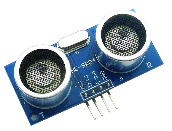
Capteur ultrasons
- Dimensions : 45 mm x 20 mm x 15 mm
- Plage de mesure : 2 cm à 400 cm
- Résolutionde la mesure: 0.3 cm
- Angle de mesure efficace : 15°
- Largeur d'impulsion sur l'entrée de déclenchement : 10 μs (Trigger Input Pulse width)
- Tension d'alimentation : 5V nominal ±0.5V
- Courant de repos : 2mA nominal ±0.5mA
- Courant de fonctionnement : 15mA nominal ±5mA
- Fréquence des ultrasons : 40kHz
Broches de connection
- Vcc= Alimentation +5 V DC
- Trig= Entrée de déclenchement de la mesure (Trigger input)
- Echo= Sortie de mesure donnée en écho (Echo output)
- GND= Masse de l'alimentation
Fonctionnement
Le capteur émet alors une série de 8 impulsions ultraso-niques à 40 kHz, puis il attend le signal réfléchi.
Lorsque celui-ci est détecté, il envoie un signal "high" sur la sortie "Echo", dont la durée est proportionnelle à la distance mesurée.
Distance de l'objet
La distance parcourue par un son se calcule en multipliant la vitesse du son, environ 340m/s (ou 34.000cm/1.000.000μs) par le temps de propagation.Soit : $d = v\cdot t$ (distance = vitesse $\times $temps).
Le HC-SR04 donne une durée d'impulsion en dizaines de μs. Il faut donc multiplier la valeur obtenue par 10μs pour obtenir le temps $t$.
On sait aussi que le son fait un aller-retour.
La distance vaut donc la moitié.
$d = \dfrac{34.000cm}{1.000.000μs}\cdot 10us \cdot \dfrac{durée}{2}$ en simplifiant $d =\dfrac{17}{100}cm \cdot durée$
La formule $d = \dfrac{durée}{58cm}$ figure aussi dans le manuel d'utilisation du HC-SR04 car la fraction 17/1000 est égale à 1/58,8235.
Elle donne cependant des résultats moins précis.
Note : A grande distance, la surface de l'objet à détecter doit mesurer au moins 0.5m².
Programme
Dans ce programme en assembleur pour processeur AVR, je prendrai un Attiny85
;                      ATtiny85-PU20
;                         +-\/-+
;                    PB5 1|-  -|8  Vcc
;             TRIG - PB3 2|-  -|7  PB2
;             ECHO - PB4 3|-  -|6  PB1
;                    GND 4|-  -|5  PB0
;                         +----+
    #define F_CPU 20000000 ;20MHz
    #define C4PUS (F_CPU/4000000) ;/4 nombre de périodes par us attention aux approximation
    .def    zero   = r10
    .def    regA   = R16       ; GENERAL PURPOSE ACCUMULATOR
    .def    VL      =r22
    .def    VH      =r23
    .equ    V=17010*10  ;Vitesse du son A/R en cm/s *10us
    .equ    US4CM=(F_CPU/V) ;us pas cm
    .equ    TRIG=PORTB3       ;  Sensor TRIG pin (Output on AVR, input on sensor)
    .equ    ECHO=PORTB4       ;  Sensor ECHO pin (Input on AVR, output on sensor)

    .cseg
.include "tn85def.inc"
    .org 0x0000

    rjmp  RESET_vect    ;  Reset Handler
    reti                ;  External Interrupt 0

    RESET_vect:
    clr     zero

loop:
    rcall   HCSR04

    rjmp    loop

HCSR04:
    ldi     XH,HIGH(C4PUS*10) ;10us
    ldi     XL,LOW(C4PUS*10)
    SBI     PORTB,TRIG        ; Start 10µs trigger pulse by setting TRIG high.
    rcall   Wait4xCycles      ; Run the delay.
    CBI     PORTB,TRIG        ; Turn off the trigger.

    clr     VH                ;Initialise le compteur de longueur
    clr     VL

;  Waits for echo to start from ultrasonic sensor.
WAIT4ONECHO:
    sbis     PINB, ECHO       ; Check ECHO line of sensor and skip if high
    rjmp     WAIT4ONECHO
    ;retour d'une longueur d'impulsion d'écho dans V .
    ; À ce stade, V aura soit le nombre de 0
    ; 512cm intervalles à l'objet ou seront nuls ,
    ; indiquant l'objet n'a pas été détecté .
GETECHOPULSE:
    inc     VL              ; [1] V=V+1 (1cm)
    adc     VH,zero         ; [1]
    cpi     VH,2            ; [1]=3 VH>=2
    brge    GEPret          ; [1]/2=4 If CNT overflows to zero, exit routine.
                            ;     Timing: false:1clk, true:2clk
    ldi     XH,HIGH(C4PUS*US4CM-1) ;us (-7) call+ret
    ldi     XL,LOW(C4PUS*US4CM-1)
    rcall   Wait4xCycles     ; Run the delay for 1cm

    sbic     PINB, ECHO     ; [1]/2=6 Check ECHO pin. If no ECHO, skip over next instruction.
                            ;     Timing: false:1clk, true:2clk
    rjmp     GETECHOPULSE   ; [2]=8
GEPret:

    cpi     VH,2            ;Sinon si XH>=2 (>511cm); objet non détecté
    brge    NoObj
    tst     VL
    brne    OBJETOK
NoObj:
    clr     VL              ;Si 0 pas d'objet
    clr     VH
OBJETOK:
    ret

;------------------------------------------------------------------------------
; Input : XH:XL - number of CPU cycles to wait (divided by four)
;------------------------------------------------------------------------------
Wait4xCycles:
    sbiw    XH:XL, 1        ; x-- (2 cycles)
    brne    Wait4xCycles    ; jump if not zero (2 cycles)
    ret
L'horloge DS3231 (RTC = Real Time Clock)
Le DS3231 est une horloge temps réel (RTC) qui contient un quartz compensée pour les dérives de température.La communication se fait via le bus i2C (broches SDA & SCL) adresse par defaut 0x68
Les dates et heures sont mémorisées grâce à une pile CR2032
Détails des octets
| ADDRESS | BIT 7 | MSB BIT 6 | BIT 5 | BIT 4 | BIT 3 | BIT 2 | BIT 1 | BIT 0 LSB | FUNCTION | RANGE |
|---|---|---|---|---|---|---|---|---|---|---|
| 0x00 | 0 | 10 Seconds | Seconds | Seconds | 00–59 | |||||
| 0x01 | 0 | 10 Minutes | Minutes | Minutes | 00–59 | |||||
| 0x02 | 0 | 12/24 | AM/PM 20 Hour | 10 Hour | Hour | Hours | 1–12 + AM/PM 00–23 | |||
| 0x03 | 0 | 0 | 0 | 0 | 0 | Day | Day | 1–7 | ||
| 0x4h | 0 | 10 Date | Date | Date | 01–31 | |||||
| 0x05 | Century | 0 | 0 | 10 Month | Month | Month/Century | 01–12 + Century | |||
| 0x06 | 10 Year | Year | Year | 00–99 | ||||||
| 0x07 | A1M1 | 10 Seconds | Seconds | Alarm 1 Seconds | 00–59 | |||||
| 0x08 | A1M2 | 10 Minutes | Minutes | Alarm 1 Minutes | 00–59 | |||||
| 0x09 | A1M3 | 12/24 | AM/PM | 10 Hour | Hour | Alarm 1 Hours | 1–12 + AM/PM 00–23 | |||
| 20 hour | ||||||||||
| 0x0A | A1M4 | DY/DT | 10 Date | Day | Alarm 1 Day | 1–7 | ||||
| Date | Alarm 1 Date | 1–31 | ||||||||
| 0x0B | A2M2 | 10 Minutes | Minutes | Alarm 2 Minutes | 00–59 | |||||
| 0x0C | A2M3 | 12/24 | AM/PM | 10 Hour | Hour | Alarm 2 Hours | 1–12 + AM/PM00–23 | |||
| 20 hour | ||||||||||
| 0x0D | A2M4 | DY/DT | 10 Date | Day | Alarm 1 Day | 1–7 | ||||
| Date | Alarm 2 Date | 1–31 | ||||||||
| 0x0E | EOSC | BBSQW | CONV | RS2 | RS1 | INTCN | A2IE | A1IE | Control | — |
| 0x0F | OSF | 0 | 0 | 0 | EN32kHz | BSY | A2F | A1F | Control/Status | — |
| 0x10 | SIGN | DATA | DATA | DATA | DATA | DATA | DATA | DATA | Aging Offset | — |
| 0x11 | SIGN | DATA | DATA | DATA | DATA | DATA | DATA | DATA | MSB of Temp | — |
| 0x12 | DATA | DATA | 0 | 0 | 0 | 0 | 0 | 0 | LSB of Temp | — |
Les Alarmes
Le DS3231 contient deux alarmes heure/jour.L'alarme 1 peut être réglée en écrivant dans les registres 07h à 0Ah.
L'alarme 2 peut être réglée en écrivant dans les registres 0Bh à 0Dh.
Les alarmes peuvent être programmées (par les bits d'activation d'alarme et INTCN du registre de contrôle) pour activer la sortie INT/SQW dans une condition de correspondance d'alarme.
Le bit 7 de chacun des registres d'alarme d'heure/de date est un bit de masque.
Lorsque tous les bits de masque pour chaque alarme sont à logique 0, une alarme se produit uniquement lorsque les valeurs dans les registres de chronométrage correspondent aux valeurs correspondantes stockées dans les registres d'alarme d'heure / de date. Les alarmes peuvent également être programmées pour se répéter toutes les secondes, minutes, heures, jours ou dates. Le tableau suivan montre les paramètres possibles.
Les configurations non répertoriées dans le tableau entraîneront un fonctionnement anormal.
| DY/DT | ALARME 1 LES BITS DE MASQUE ENREGISTRER(BIT 7) | Type D'ALARME | |||
| A1M4 | A1M3 | A1M2 | A1M1 | ||
| X | 1 | 1 | 1 | 1 | Alarme une fois par seconde |
| X | 1 | 1 | 1 | 0 | Alarme lorsque les secondes correspondent |
| X | 1 | 1 | 0 | 0 | Alarme lorsque les minutes et les secondes correspondent |
| X | 1 | 0 | 0 | 0 | *Alarme lorsque les heures, les minutes et les secondes correspondent |
| 0 | 0 | 0 | 0 | 0 | Alarme lorsque la date, les heures, les minutes et les secondes correspondent |
| 1 | 0 | 0 | 0 | 0 | Alarme lorsque le jour, les heures, les minutes et les secondes correspondent |
| DY/DT | ALARME 2 LES BITS DE MASQUE ENREGISTRER(BIT 7) | Type D'ALARME | |||
| A1M4 | A1M3 | A1M2 | |||
| X | 1 | 1 | 1 | Alarme une fois par minute (00 secondes de chaque minute) | |
| X | 1 | 1 | 0 | Alarme lorsque les minutes correspondent | |
| X | 1 | 0 | 0 | *Alarme lorsque les heures et les minutes correspondent | |
| 0 | 0 | 0 | 0 | Alarme lorsque la date, les heures et les minutes correspondent | |
| 1 | 0 | 0 | 0 | Alarme lorsque le jour, les heures et les minutes correspondent | |
Si la validation d'interruption d'alarme correspondante 'A1IE' ou 'A2IE' est également définie sur la logique 1 et le bit INTCN est réglé sur la logique 1, la condition d'alarme activera le signal INT/SQW.
La correspondance est testée sur la mise à jour une fois par seconde des registres d'heure et de date.
| Bit 7 | Bit 6 | Bit 5 | Bit 4 | Bit 3 | Bit 2 | Bit 1 | Bit 0 | |
| Nom | OFS | 0 | 0 | 0 | EN32kHz | BSY | A2F* | A1F* |
| Postion | 1 | 0 | 0 | 0 | 1 | X | X | X |
Ce bit contrôle le signal INT/SQW. Lorsque le bit INTCN est défini sur la logique 0, une onde carrée est émise sur la broche INT/SQW.
Lorsque le bit INTCN est réglé sur la logique 1, une correspondance entre les registres de chronométrage et l'un des registres d'alarme active la sortie INT/SQW (si l'alarme est également activée).
L'indicateur d'alarme correspondant est toujours défini quel que soit l'état du bit INTCN.
Le bit INTCN est réglé sur la logique 1 lors de la première mise sous tension
Status Register Bit 1: activation de l'interruption d'alarme 2 (A2IE).
Lorsqu'il est défini sur la logique 1, ce bit permet au bit d'indicateur d'alarme 2 (A2F) dans le registre d'état d'affirmer INT/SQW (lorsque INTCN = 1).
Lorsque le bit A2IE est défini sur la logique 0 ou INTCN est défini sur la logique 0, le bit A2F n'initie pas de signal d'interruption.
Le bit A2IE est désactivé (logique 0) lors de la première mise sous tension Bit 0: activation de l'interruption d'alarme 1 (A1IE). Lorsqu'il est défini sur la logique 1, ce bit permet au bit indicateur d'alarme 1 (A1F) dans le registre d'état d'affirmer INT/SQW (lorsque INTCN = 1). Lorsque le bit A1IE est défini sur la logique 0 ou INTCN est défini sur la logique 0, le bit A1F n'initie pas le signal INT/SQW. Le bit A1IE est désactivé (logique 0) lors de la première mise sous tension.
| Bit 7 | Bit 6 | Bit 5 | Bit 4 | Bit 3 | Bit 2 | Bit 1 | Bit 0 | |
| Nom | EOSC | BBSQW | CONV | RS2 | RS1 | INTCN* | A2IE* | A2IE* |
| Postion | 1 | 0 | 0 | 0 | 1 | X | X | X |
Une logique 1 dans le bit de drapeau d'alarme 2 indique que le temps correspond aux registres d'alarme 2.
Si le bit A2IE est la logique 1 et le bit INTCN est défini sur la logique 1, la broche INT/SQW est également activée.
A2F est effacé lors de l'écriture dans la logique 0.
La tentative d'écriture dans la logique 1 laisse la valeur inchangée.
Bit 0: indicateur d'alarme 1 (A1F).
Une logique 1 dans le bit de drapeau d'alarme 1 indique que le temps correspond à l'enregistrement de l'alarme 1.
Si le bit A1IE est la logique 1 et le bit INTCN est défini sur la logique 1, la broche INT/SQW est également activée. A1F est effacé lorsqu'il est écrit dans la logique 0.
Ce bit ne peut être écrit que dans la logique 0.
Toute tentative d'écriture dans la logique 1 laisse la valeur inchangée.
Drapeau d'arrêt de l'oscillateur (OSF).Une logique 1 dans ce bit indique que l'oscillateur est arrêté ou a été arrêté pendant une certaine période et peut être utilisé pour juger de la validité des données de chronométrage. Ce bit est mis à la logique 1 chaque fois que l'oscillateur s'arrête.
Voici des exemples de conditions pouvant entraîner la définition du bit OSF:
- La première fois que l'alimentation est appliquée.
- Les tensions présentes à la fois sur VCC et VBAT sont insuffisantes pour supporter l'oscillation.
- Le bit EOSC est désactivé en mode alimenté par batterie.
- Influences externes sur le cristal (c.-à-d. , bruit, fuite, etc.).
Température
La température est codé sur 10 bits avec une résolution de 0,25°C et est accessible aux emplacements 11h et 12h.La température est codée au format complément à deux. Les 8 bits supérieurs, la partie entière, sont à l'emplacement 11h et les 2 bits inférieurs, la partie fractionnaire, sont dans le quartet supérieur à l'emplacement 12h.
Par exemple, 00011001 01b = + 25,25 ° C. Lors de la réinitialisation de l'alimentation, les registres sont réglés sur une température par défaut de 0 ° C et le contrôleur démarre une conversion de température.
La température est lue lors de la première application de l'accès VCC ou I2C sur VBAT et une fois toutes les 64 secondes par la suite.
Les registres de température sont mis à jour après chaque conversion initiée par l'utilisateur et à chaque conversion de 64 secondes.
Les registres de température sont en lecture seule.
Le magnétomètre sur 3 axes HMC5883L
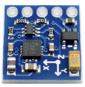
Caractéristique du HMC5883L
Triple module d'axe HMC5883L de boussole capteur de magnétomètre I²C (7-bit address : 0x1E) avec alimentation de 3,3 V ou 5V. La taille du module est: 16x18mm.un ADC 12 bits qui permet une précision de cap de la boussole de 1° à 2° degrés.
Cet appareil prend en charge les modes standard (100 kHz) et rapide (400 kHz), mais ne prend pas en charge le mode haute vitesse (Hs).
Des résistances pull-up externes sont nécessaires pour prennent en charge ces modes de vitesse standard et rapide.
Faible consommation d'énergie (100 μA)
Pour comprendre l'I²C:
| 7-bit address | 0x1E | 0001 1110 |
| 8-bit read address | 0x3D | 0011 1101 |
| 8-bit write address | 0x3C | 0011 1100 |
Modes de fonctionnnements
Continuous-Measurement Mode
En mode de mesure continue, l'appareil effectue des mesures en continu, à une fréquence sélectionnable par l'utilisateur, et place les données mesurées dans les registres de sortie de données.Single-Measurement Mode
Il s'agit du mode de mise sous tension par défaut. En mode de mesure unique, l'appareil effectue une seule mesure et place les données mesurées dans des registres de sortie de données. Une fois la mesure terminée et les registres de données de sortie sont mise à jour, l'appareil est placé en mode inactif et le registre de mode passe en mode inactif.Idle Mode
Pendant ce mode, l'appareil est accessible via le bus I2C, mais les principales sources de consommation d'énergie sont désactivées, tels que le CAN, l'amplificateur et le courant de polarisation du capteur.Tous les registres conservent leurs valeurs lorsqu'ils sont inactifs. Le bus I²C est activé pour être utilisé par d'autres appareils sur le réseau en mode inactif.
Les registres
| Address Location | Name | Access |
|---|---|---|
| 00 | Configuration Register A | Read/Write |
| 01 | Configuration Register B | Read/Write |
| 02 | Mode Register | Read/Write |
| 03 | Data Output X MSB Register | Read |
| 04 | Data Output X LSB Register | Read |
| 05 | Data Output Z MSB Register | Read |
| 06 | Data Output Z LSB Register | Read |
| 07 | Data Output Y MSB Register | Read |
| 08 | Data Output Y LSB Register | Read |
| 09 | Status Register | Read |
| 0A | Identification Register A | Read |
| 0B | Identification Register B | Read |
| 0C | Identification Register C | Read |
Accès aux registres
Les dispositifs utilisent un pointeur d'adresse pour indiquer quel emplacement de registre doit être lu ou écrit. Ces emplacements de pointeur sont envoyés du maître à ce dispositif esclave et succèdent à l'adresse de 7 bits plus l'identifiant de lecture/écriture de 1 bit.Pour minimiser la communication entre le maître et cet appareil, le pointeur d'adresse est mis à jour automatiquement sans intervention du maître. Cette mise à jour automatique du pointeur d'adresse comporte deux fonctionnalités supplémentaires. Premièrement, lorsque l'adresse 12 ou supérieure est accessible, le pointeur se met à jour à l'adresse 00 et deuxièmement, lorsque l'adresse 08 est atteinte, le pointeur revient à l'adresse 03.
Logiquement, le fonctionnement du pointeur d'adresse fonctionne comme indiqué ci-dessous.
Si (pointeur d'adresse = 08) alors pointeur d'adresse = 03
Sinon si (pointeur d'adresse >= 12) alors pointeur d'adresse = 0
Sinon (pointeur d'adresse) = (pointeur d'adresse) + 1
Par exemple, pour déplacer le pointeur d'adresse vers le registre 10, envoyez 0x3C 0x0A.
Configuration Register A
Le registre de configuration est utilisé pour configurer l'appareil afin de régler le débit de sortie des données et la configuration de la mesure.| Broche | CRA7 | CRA6 | CRA5 | CRA4 | CRA3 | CRA2 | CRA1 | CRA0 |
|---|---|---|---|---|---|---|---|---|
| Nom | - | MA1 | MA0 | DO2 | DO1 | DO0 | MS1 | MS0 |
| Default | 1 | 1 | 1 | 1 | 0 | 0 | 0 | 0 |
| Default | 1 | MA: 0b11 | DO=0b100 | MS=0b00 | ||||
CRA0 à CRA7 indiquent les emplacements des bits, CRA désignant les bits qui se trouvent dans le registre de configuration.
CRA7 désigne le premier bit du flux de données.
| Location | Name | Description |
|---|---|---|
| CRA7 | Ce bit doit être effacé pour un fonctionnement correct. | |
| CRA6-5 | MA1-0 | Sélectionner le nombre d'échantillons moyennés (1 à 8) par sortie de mesure. 00 = 1 ; 01 = 2 ; 10 = 4 ; 11 = 8 (par défaut) |
| CRA4-2 | DO2-0 | Bits de débit de sortie de données. Ces bits définissent la vitesse à laquelle les données sont écrites dans les trois registres de sortie de données. |
| CRA1-0 | MS1-0 | Bits de configuration de mesure. Ces bits définissent le flux de mesure de l'appareil, en particulier s'il faut ou non incorporer un biais appliqué dans la mesure. |
Le tableau ci-dessous montre tous les débits de sortie sélectionnables en mode de mesure continue.
Les trois canaux doivent être mesurés dans un débit de sortie donné.
D'autres débits de sortie avec un débit maximal de 160 Hz peuvent être obtenus en surveillant la broche d'interruption DRDY en mode de mesure unique.
| DO2 | DO1 | DO0 | Taux de sortie de données |
|---|---|---|---|
| 0 | 0 | 0 | 0.75 |
| 0 | 0 | 1 | 1.5 |
| 0 | 1 | 0 | 3 |
| 0 | 1 | 1 | 7.5 |
| 1 | 0 | 0 | 15 (default) |
| 1 | 0 | 1 | 30 |
| 1 | 1 | 0 | 75 |
| 1 | 1 | 1 | Non utilité |
| MS1 | MS0 | Mode de mesure |
|---|---|---|
| 0 | 0 | Configuration de mesure normale (par défaut). En configuration de mesure normale, l'appareil suit le flux de mesure normal. Les broches positives et négatives de la charge résistive sont laissées flottantes et à haute impédance. |
| 0 | 1 | Configuration de polarisation positive pour les axes X, Y et Z. Dans cette configuration, un courant positif est forcé à travers la charge résistive pour les trois axes. |
| 1 | 0 | Configuration de polarisation négative pour les axes X, Y et Z. Dans cette configuration, un courant négatif est forcé à travers la charge résistive pour les trois axes. |
| 1 | 1 | Cette configuration est réservée. |
Configuration Register B
Le registre de configuration B pour régler le gain de l'appareil.| Broche | CRB7 | CRB6 | CRB5 | CRB4 | CRB3 | CRB2 | CRB1 | CRB0 |
|---|---|---|---|---|---|---|---|---|
| Nom | GN2 | GN1 | GN0 | - | - | - | - | - |
| Default | 0 | 0 | 1 | 0 | 0 | 0 | 0 | 0 |
| Default | GN:0b001 | 0b00000 | ||||||
La configuration de gain est commune à tous canaux.
| GN2 | GN1 | GN0 | Plage de champ de détection recommandée | Gain(LSB/Gauss) | Plage de sortie |
|---|---|---|---|---|---|
| 0 | 0 | 0 | ± 0.88 Ga | 1370 | 0xF800–0x07FF (-2048–2047 ) |
| 0 | 0 | 1 | ± 1.3 Ga | 1090 (Default) | |
| 0 | 1 | 0 | ± 1.9 Ga | 820 | |
| 0 | 1 | 1 | ± 2.5 Ga | 660 | |
| 1 | 0 | 0 | ± 4.0 Ga | 440 | |
| 1 | 0 | 1 | ± 4.7 Ga | 390 | |
| 1 | 1 | 0 | ± 5.6 Ga | 330 | |
| 1 | 1 | 1 | ± 8.1 Ga | 230 |
Mode Register
Ce registre de mode est un registre de 8 bits à partir duquel des données peuvent être lues ou dans lequel des données peuvent être écrites.Ce registre sert à sélectionner le mode de fonctionnement de l'appareil.
| Broche | MR7 | MR6 | MR5 | MR4 | MR3 | MR2 | MR1 | MR0 | |||
|---|---|---|---|---|---|---|---|---|---|---|---|
| Nom | - | - | - | - | - | - | MD1 | MD0 | |||
| Default | 1 | 0 | 0 | 0 | 0 | 0 | 0 | 1 | |||
| Default | 0b100000 | MR:0b01 | |||||||||
| MD1 | MD0 | Description |
|---|---|---|
| 0 | 0 | Mode de mesure continue. En mode de mesure continue, l'appareil effectue en continu des mesures et place le résultat dans le registre de données. RDY passe à l'état haut lorsque de nouvelles données sont placées dans les trois registres. Après une mise sous tension ou une écriture dans le registre de mode ou de configuration, le premier ensemble de mesures est disponible à partir des trois registres de sortie de données après une période de 2/fDO et les mesures suivantes sont disponibles. |
| 0 | 1 | Mode de mesure unique (par défaut). Lorsque le mode de mesure unique est sélectionné, l'appareil effectue une seule mesure, définit RDY haut et revient en mode veille. Le registre de mode revient aux valeurs de bit du mode inactif. La mesure reste dans le registre de sortie de données et RDY reste haut jusqu'à ce que le registre de sortie de données soit lu ou qu'une autre mesure soit effectuée |
| 1 | 0 | Idle Mode. Mode inactif. L'appareil est placé en mode veille. |
| 1 | 1 | Idle Mode. Mode inactif. L'appareil est placé en mode veille. |
Data Output X, Y, Z Registers A and B
La valeur stockée dans ces deux registres est un Valeur 16 bits sous forme de complément à 2, dont la plage est comprise entre 0xF800 et 0x07FF. A contient le MSB et B le LSB.Least Significant Bit, ou LSB bit de poid faible
Most Significant Bit, ou MSB bit de poids fort
DXRA7 et DXRB7 désignent le premier bit du flux de données.
Lorsqu'un ou plusieurs registres de sortie sont lus, de nouvelles données ne peuvent être placées dans aucun des registres de données de sortie jusqu'à ce que tous six registres de sortie de données (X,Y,Z) soient lus.
Cette exigence a également un impact sur DRDY et RDY, qui ne peuvent pas être effacés jusqu'à ce que de nouveaux les données sont placées dans tous les registres de sorties.
Status Register
Le registre d'état est un registre 8 bits en lecture seule.| Broche | SR7 | SR6 | SR5 | SR4 | SR3 | SR2 | SR1 | SR0 | |||
|---|---|---|---|---|---|---|---|---|---|---|---|
| Nom | - | - | - | - | - | - | LOCK | RDY | |||
| Default | 0 | 0 | 0 | X | 0 | 0 | 0 | 1 | |||
| Default | 0b000X00 | SR:0b00 | |||||||||
LOCK
Verrouillage du registre de sortie des données. Ce bit est activé lorsque certains des six registres de sortie de données, mais pas tous, ont été lus.Lorsque ce bit est défini, les six registres de sortie de données sont verrouillés et aucune nouvelle donnée ne sera placée dans ces registres tant que l'une des trois conditions n'est pas remplie :
- les six octets ont été lus ou le mode a changé
- le mode est changé.
- la configuration de mesure est modifiée.
RDY
Bit prêt. Défini quand les données sont écrites dans les six registres de données.Effacé lorsque l'appareil lance une écriture dans les registres de sortie de données et après qu'un ou plusieurs registres de sortie de données ont été écrites.
Lorsque le bit RDY est à 0, il doit rester à 0 pendant 250 μs.
La broche DRDY peut être utilisée comme alternative au registre d'état pour surveiller l'appareil pour les données de mesure.
Identification Register A, B, C
Le registre d'identification A sert à identifier le dispositif. La valeur d'identification de cet appareil est stockée dans ce registre.Il s'agit d'un registre en lecture seule. Les Valeurs ASCII des registres A,B,C sont "H43"
Calibration
Une méthode d'étalonnage simple peut être utilisée pour déterminer les valeurs de décalage et de facteur d'échelle :Placer la boussole sur une surface horizontale et faite la tourner plusieurs fois sur elle même.
Trouvez les valeurs maximales et minimales des lectures magnétiques X et Y.
À l'aide de ces quatre valeurs, déterminez les facteurs d'échelle X et Y (Xsf, Ysf) et les valeurs de décalage d'origine (Xoff, Yoff).
Xsf = 1 ou (Ymax - Ymin) / (Xmax - Xmin), le plus grand des deux
Ysf = 1 ou (Xmax - Xmin) / (Ymax - Ymin), le plus grand des deux
Xoff = [(Xmax - Xmin)/2 - Xmax] * Xsf
Yoff = [(Ymax - Ymin)/2 - Ymax] * Ysf
L'exemple suivant montre comment les valeurs de compensation sont déterminées.
Une boussole est montée dans une voiture qui a parcouru un cercle dans un parking vacant.
Les comptes magnétiques X et Y (15 000 comptes = 1 gauss) du magnétomètre sont balayés et les lectures minimales et maximales sont :
Xmin = -3298 Xmax = 2338
Ymin = -3147 Ymax = 1763
Comme (Ymax - Ymin) / (Xmax - Xmin)=0.87118523775727
et comme cette valeur est inférieure à 1 alors Xsf=1
Comme (Xmax - Xmin) / (Ymax - Ymin)=1.1478615071283
et comme cette valeur est supérieur à 1 alors Ysf=1.1478615071283
Calculez les valeurs de correction de décalage en prenant la moitié de la différence des valeurs max.-min.
lectures et appliquer les facteurs d'échelle, Xsf et Ysf
Xoff = [(Xmax - Xmin)/2 - Xmax] * Xsf = 480
Yoff = [(Ymax - Ymin)/2 - Ymax] * Ysf = 794.32016293279
Stockez ces valeurs et appliquez-les à chaque lecture compensée en inclinaison - XH et XH.
Les nombres Valeur et Valeur utilisés dans les calculs d'azimut, pour déterminer le cap compas sont :
Xvalue = XH + 480.00
Yvalue = 1.15 * YH + 794.32
Bonus guidage
En bonus, ci-dessous un petit programme de guidage par boussole
    #include <Wire.h>
#include <HMC5883L.h>

HMC5883L compass;

float angle=0;
//Calculate magnetic declination according to your location
//See http://magnetic-declination.com
//Or https://www.ngdc.noaa.gov/geomag/calculators/magcalc.shtml?#declination

float declinationAngle = (0.0 + (48.0 / 60.0)) / (180 / PI);
//Ajoute 0.11
//Pour les moteurs
int target=180;
int cap=0;
int speedLeft;
int speedRight;
void setup()
{
  Serial.begin(9600);
  // Initialize Initialize HMC5883L
  while (!compass.begin())
  {
    delay(500);
  }
  //Serial.println(F("Signature HMC5883L : 'A48'"));
  // Set measurement range
  compass.setRange(HMC5883L_RANGE_1_3GA);
  // Set measurement mode
  compass.setMeasurementMode(HMC5883L_CONTINOUS);
  // Set data rate
  compass.setDataRate(HMC5883L_DATARATE_30HZ);
  // Set number of samples averaged
  compass.setSamples(HMC5883L_SAMPLES_8);
}

void loop()
{
  Vector mag = compass.readRaw();

  angle=atan2((mag.YAxis*1.02407002188184+ 180),(mag.XAxis -105))*180/PI;
  angle -= declinationAngle;
  if (angle<0) angle+=360;

  /*
   *
   *  Pilotage du véhicule
   *
   *
  */
  cap=(int)angle;
  // how many degrees are we off
  int diff = cap-target;

  // modify degress
  if (diff > 180) {
    diff = -360 + diff;
  } else if (diff < -180) {
    diff = 360 + diff;
  }

  // Make the robot turn to its proper orientation
  diff = map(diff, -180, 180, -255, 255);

 if (diff > 0) {
    // keep the right wheel spinning,
    // change the speed of the left wheel
    speedLeft = 255 - diff;
    speedRight = 255;
  } else {
    // keep the right left spinning,
    // change the speed of the left wheel
    speedLeft = 255;
    speedRight = 255 + diff;
  }
  Serial.print(F("XY:"));
  Serial.print(angle);
  Serial.print(F("°\tTarget:"));
  Serial.print(target);
  Serial.print(F("\tCap:"));
  Serial.print(cap);
  Serial.print(F("\tGauche:"));
  Serial.print(speedLeft);
  Serial.print(F("\tDroite:"));
  Serial.println(speedRight);
  delay(250);
}
Le Lidar
 | Ce LiDAR fait maison a un Ø52mm pour une longueur de 78,5mm Il fonctionne sous 5V. Protocoles de liaisons point à point série UART a 115200bauds, parité "none", 8 bits,1 bit de stop. Suivant la vitesse de rotation du motoréducteur N20, la vitesse de balayage $Z_{moteur}=10dts, Z_{couronne}=32dts$ $N_{couronne}=\dfrac{N_{moteur}\cdot Z_{moteur}}{Z_{couronne}}$ Mon motoréducteur tourne a 40min-1, donc ma couronne tourne à 12,50 min-1. soit $0,21tr\cdot s^{-1}$, ce qui représente 75°/s. Avec une mesure à 30Hz, entre chaque mesure 2,5°. A une distance de 3m, cela représente 130,9mm, de default de lecture. |
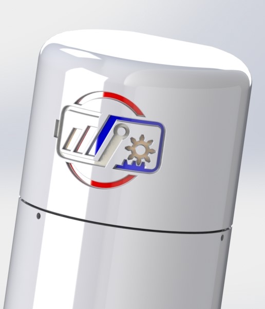 | |
| Le LiDAR (Light Detection And Ranging),est une méthode de télédétection et de télémétrie semblable au radar, mais qui émet des impulsions de lumière infrarouge, au lieu d'ondes radio, puis en mesure le temps de retour après avoir été réfléchies sur des objets à proximité. |
Liste du matériel
| Image | Désignation | Fournisseur | Prix | Stock | Nécessaire |
|---|---|---|---|---|---|
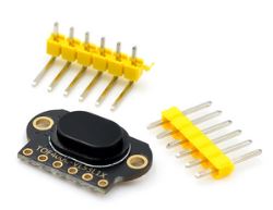 | Module de capteur de distance Laser, TOF400C VL53L1X 4m I²C library : VL53L0X adresse : (0x29) | aliexpress | 6,35€ | 1 | 1 |
 | 3-6V DC Arbre court Couple type N20 reducteur Moteur de Boite a vitesse
| amazone | 1,51€ | 2 | 1 |
 | Anneau de glissement de Capsule 10 canaux 2A 22mm, Ø22mm de diamètre, 10 voies 2A, aiguille de brosse interne plaquée or et bague de glissement, fils avant et arrière 90mm Le courant nominal de chaque canal est de 2A et la tension nominale est de 240VAC.
| aliexpress | 4,76€ | 1 | 1 |
 | Balles de tir en acier inoxydable, Ø5mm | aliexpress | 0,023€ | 200 | 10 |
 | Ensembles broche à angle Droit Pas 2.54mm Pin Header Connecteur Adaptateur JST XH 4P M/F | aliexpress | 0,056€ | 20 | 1 |
 | US1881 TO92 capteur d'effet Hall détecteur magnétique 3.5V à 24V 5mA | aliexpress | 0,10€ | 10 | 1 |
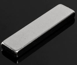 | Aimant Rectangle Néodyme N52 Terres Rares
| aliexpress | 0,714€ | 6 | 1 |
| Un microcontrolleur | 1 | ||||
| Un module de pilote de moteur à courant continu | 1 |
Le cablage
| Les branchement du LiDAR, après reflection, les informations en entrée et en sortie. Choix du protocole : Série, pour sa simplicité d'émission et réception des informations. En entrée: Possibilité d'envoyer une commande via le bus série 3.3V ou 5V, pour ne tenir en compte que de certains angles seul secteur. En sortie: Liste de données comportant l'angle et la distance uniquement. | |
Le nombre de fils
| fils μC | min | max | |
|---|---|---|---|
| Moteur | 1 | 2 | |
| Hall | 1 | 1 | |
| TOF400 | 2 | 4 | |
| Comm Ext | 2 | 2 | |
| TOTAL | 6 | 9 |